
Every smart device starts as an idea. Maybe it is a tiny fitness tracker. Maybe it is a coffee machine that knows your mood. Maybe it is a robot that waters your basil. Before it can beep, blink, buzz, or connect to Wi Fi, it needs a printed circuit board, also called a PCB. And that PCB needs assembly.
TLDR: PCB assembly turns a bare circuit board into a working electronic device. It adds tiny parts, solders them in place, checks for mistakes, and tests the final board. A prototype proves the idea. Production makes it ready for real customers.
What Is PCB Assembly?
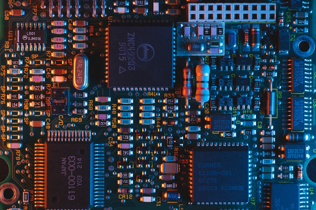
Think of a PCB as a tiny city. The copper tracks are roads. The components are buildings. Electricity is the traffic. The design tells everything where to go.
But a bare PCB cannot do much. It is like a pizza base with no toppings. PCB assembly adds the toppings. These toppings are parts like:
- Resistors, which control electric current.
- Capacitors, which store tiny bursts of energy.
- Microchips, which act like little brains.
- Connectors, which let the board talk to other parts.
- LEDs, which make things blink in a very satisfying way.
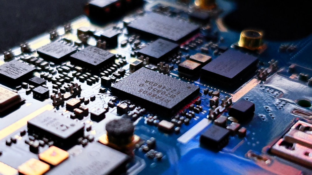
Once these parts are placed and soldered, the board can come alive. It can sense, compute, charge, move, or communicate. In short, it becomes useful.
Step One: The Prototype
A prototype is the first working version of a product. It does not need to be perfect. It needs to answer one big question. Does this idea work?
At this stage, engineers are still learning. They may change the layout. They may swap parts. They may discover that one chip gets too hot. Or that one button is in a silly place. This is normal. Prototypes are made for learning.
A prototype can be hand assembled. It may look a bit messy. It may have wires sticking out. It may have labels written with a marker. That is okay. A prototype is not trying to win a beauty contest. It is trying to prove a point.
Here is what teams check during prototyping:
- Function: Does the circuit do what it should?
- Power: Does it use too much energy?
- Heat: Does anything get dangerously warm?
- Size: Will it fit inside the product case?
- Cost: Can it be made at a fair price?
This stage can be exciting. It can also be annoying. Sometimes the board works on Monday and refuses to work on Tuesday. Electronics can be dramatic.
Step Two: The Design Files
Before a board can be assembled, the manufacturer needs instructions. These files explain the design in detail. They are like a recipe, a map, and a shopping list all in one.
The key files often include:
- Gerber files: These show the PCB layers and copper paths.
- Bill of materials: This lists every part needed.
- Pick and place file: This tells machines where each part goes.
- Assembly drawing: This helps humans review the board.
The bill of materials is very important. People call it the BOM. It includes part names, quantities, values, and supplier details. If the BOM has mistakes, trouble follows. The wrong resistor can make a sensor lie. The wrong chip can make the board do absolutely nothing. That is not a fun party trick.
Step Three: Choosing the Right Parts
Parts matter. A lot. A tiny component can decide if a product is reliable or flaky. It can also decide if the product is affordable or expensive.
For prototypes, teams may choose parts that are easy to buy. For production, they must think bigger. Can the part be ordered in large quantities? Will it still be available next year? Does it come from a trusted supplier?
This is called component sourcing. It sounds boring. It is not. It is a bit like shopping for ingredients before running a restaurant. If your special sauce disappears, your menu is in trouble.
Good sourcing helps avoid delays. It also helps avoid fake parts. Counterfeit electronics are a real problem. They may look right. They may even have the right markings. But inside, they can be weak, old, or totally wrong.
Step Four: Solder Paste Gets Ready
Now the fun starts. For many modern boards, assembly begins with solder paste. This is a gray, sticky mix of tiny metal balls and flux. It looks a bit like metallic frosting. Please do not eat it.
The solder paste is spread onto the PCB using a stencil. The stencil has tiny openings. Paste only lands where components will sit. This step must be very accurate. Too much paste can cause short circuits. Too little paste can make weak connections.
Imagine putting glue on a model airplane. If the glue goes everywhere, the result is sad. If there is no glue, the wings fall off. Solder paste has the same kind of pressure.
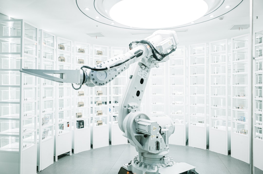
Step Five: Pick and Place Magic
Next, machines place the components. This is called pick and place. The machine picks up tiny parts from reels or trays. Then it places them on the board at high speed.
These machines are fast. Very fast. They can place thousands of parts every hour. They also have cameras. The cameras help line up each component with great care. Some parts are smaller than a grain of rice. Some are smaller than a sprinkle. Electronics really likes tiny things.
The parts sit on the solder paste. They are not fully attached yet. They are just waiting for heat to seal the deal.
Step Six: Reflow Soldering
After placement, the board goes into a reflow oven. This is not like a kitchen oven, even though the idea is similar. The board moves through heated zones. The solder paste melts. Then it cools. When it cools, it forms strong metal joints.
This is the moment when components become truly connected to the board. It is like a tiny metal handshake.
The temperature must be controlled. Too cool, and solder will not melt well. Too hot, and parts may be damaged. The oven follows a special temperature curve called a thermal profile. That sounds fancy. It means the board gets heated and cooled in a careful way.
Step Seven: Through Hole Parts
Not every component sits flat on the surface. Some parts have legs that pass through holes in the PCB. These are called through hole components.
They are often used for parts that need strength. Examples include large connectors, switches, and power parts. These parts may be soldered by hand or by a machine using wave soldering.
Surface mount parts are small and great for compact products. Through hole parts are stronger and easier to handle. Many boards use both. It is a team sport.
Step Eight: Inspection
Now the board needs a careful look. Nobody wants a hidden mistake. A tiny solder bridge can stop a whole product. One missing part can turn a smart gadget into a fancy paperweight.
Inspection can include:
- Visual inspection: People check the board with eyes and tools.
- Automated optical inspection: Cameras scan the board for errors.
- X ray inspection: Machines look under chips with hidden joints.
Automated optical inspection is often called AOI. It compares the real board to the expected design. It can spot crooked parts, missing parts, wrong parts, and solder problems.
X ray inspection is used when solder joints cannot be seen from outside. This happens with parts like ball grid array chips. These chips hide their connections underneath. Sneaky chips.
Step Nine: Testing the Board
Inspection checks how the board looks. Testing checks how the board behaves. Both are needed.
A board can look perfect and still fail. A tiny internal issue may cause trouble. Testing helps catch that before the product reaches users.
Common tests include:
- Continuity tests: These check if electrical paths connect correctly.
- In circuit tests: These test parts while they are on the board.
- Functional tests: These make the board perform real tasks.
- Burn in tests: These run the board for a long time to find weak units.
Functional testing is especially useful. If the board is for a smart lamp, the test may turn the light on and off. If it is for a sensor, the test may check readings. If it is for a robot, the test may make motors spin. Hopefully in the right direction.
From One Board to Many Boards
Making one working board is wonderful. Making ten is better. Making ten thousand is a whole new adventure.
This is the move from prototype to production. The goal changes. In prototyping, the goal is learning. In production, the goal is repeatability. Every board should work the same way. Every time.
Production requires planning. The assembly line must be set up. Machines must be programmed. Parts must be ready. Quality checks must be defined. Packaging must be prepared. Shipping must be planned.
A small mistake can become a big problem at scale. If one prototype has a bad connector, that is annoying. If five thousand units have bad connectors, that is a headache wearing tap shoes.
Design for Manufacturing
A product may work as a prototype but still be hard to manufacture. This is where design for manufacturing comes in. People often call it DFM.
DFM means designing the board so it is easier, faster, and cheaper to build. It also means fewer mistakes.
Good DFM can include:
- Using parts that machines can place easily.
- Leaving enough space between components.
- Choosing standard part sizes when possible.
- Avoiding layouts that trap heat.
- Adding test points for easier testing.
DFM is not about making the design boring. It is about making the design buildable. A brilliant design that cannot be made is like a rocket with no fuel. Impressive, but not going anywhere.
Quality Control Keeps the Party Safe
Quality control is the guardian of production. It checks that every step is done right. It also helps find patterns. If the same mistake appears again and again, the process must be fixed.
Quality control may track solder quality, placement accuracy, test results, and material batches. This data is useful. It tells the team what is working and what needs attention.
Good production is not based on luck. It is based on process. It is also based on asking annoying questions before customers have to ask them.
Why PCB Assembly Matters
PCB assembly is where design becomes reality. It connects imagination to hardware. It turns drawings into devices you can hold. Without it, our modern world would be very quiet.
No smart watches. No game consoles. No drones. No medical monitors. No electric toothbrushes that judge your brushing habits. PCB assembly supports all of this.
It is easy to forget the tiny board inside a device. But that board is the nervous system. It tells the product what to do. It listens to sensors. It controls power. It sends signals. It makes the magic feel normal.
Final Thoughts
The journey from prototype to production is full of steps. Each one matters. The prototype proves the idea. The design files explain the plan. The parts bring the circuit to life. The assembly process puts everything together. Inspection and testing make sure it works.
PCB assembly may seem complex at first. But at its heart, it is simple. Put the right parts in the right places. Connect them the right way. Test them with care. Then do it again and again.
That is how a sketch becomes a gadget. That is how a dream becomes a device. And yes, that is how a tiny board full of dots and lines can become the next big thing in your pocket.